What is entity-relationship model?
Image by Samuel Mann
A relational database, as we all know from the previous article, stores relations between integers, strings and other simple types in a very plain way: it just enumerates all values related.
This model is extremely flexible, since other relations can be easily derived from existing ones using mathematical formulae, and the relational database takes care of that.
However, database should reflect the real world in some way to be really of use. Since the relational databases store relations between mathematical abstractions and not real world things, we should make some kind of a mapping of ones to the others.
This is what entity-relationship model is for.
An entity-relationship model, as one can easily guess from its name, models relationships between entities.
But since we know that databases do essentially the same, how does it differ from the database model?
- An entity-relationship model states which data and relations between them should be stored
- A database model states how these relations are stored
In other words, ER model is design and database model is one of the ways to implement it. ER model is said to be above the database model in the waterfall developement.
Note that in both cases I use the word stored above. The model says nothing of data and relations between them that may or should exist, only of those that should be stored. Every human being participates in thousands if not millions relationships, but an ER model should state which of them are to be stored, and a relational model should decide how to store them. Of course it would be nice to store them all (and police and insurance would be just happy), but the technology does not allow it yet. Don't know whether it is good or bad.
A typical entity-relationship diagram in Peter Chen's notation looks like this:

What does it mean?
Entities
Square boxes mean entites. What do we describe in our database?
In our case, the model requires that we store information about clients, orders and
items ordered.
Square boxes are useless without additional information. Store some information? OK, we do. We just make a file to which a new line is added each time a new customer registers:
A customer has registered
A customer has registered
A customer has registered
…
, another file to which a new line is added when an order is made:
An order is made
An order is made
An order is made
…
and a third file to keep the list of items ordered.
An item is ordered
An item is ordered
…
Quite useless, right? However, there still is some information, as per request. We know that each row in the files describe a customer, an order or an item, and we can get the total number of customers, orders and items we've had so far.
This is better than nothing but still far from being usable.
Note that the diagram tells us nothing of how they should be stored. We could write them into a file, or on a paper or carve it on a stone.
Relationships
Diamonds mean relationships. How the entities are related to each other?
We see that we should store the relationships between orders and clients as well as those between items and orders.
More than that: tiny arrows between the diamonds and the boxes (that is, between the entities and relationships) show us which relationships should we store.
In our cases, we have a 1:(0-N) relationship between clients and orders and a 1:(0-N) relationship between orders and clients.
1:(0-N) is spelled as one to zero, one or many
That means that our database should make sure that any order is related to exactly one client.
Want to store an order? Be prepared to link it to the piece of information about the client who made it and make sure this information describes exactly one client. This is the database developer's task.
However, a client can have an arbitrary number of orders: no orders at all, one order or many orders. The database should provide an ability to store the clients and orders this way.
Again, the entity-relationship model does not prescribe how should we store that data, as long as the storage method satisfies the conditions above.
We could store it in two files and relate them using the row numbers:
A customer has registered
A customer has registered
A customer has registered
…
An order is made by the customer described on line 1
An order is made by the customer described on line 2
An order is made by the customer described on line 2
, or we can just keep the information in a single text file:
A client has registered
Made an order
A client has registered
Made an order
Made an order
…
, or keep it in an XML file:
<root>
 <client>
   <order/>
 </client>
 <client>
   <order/>
   <order/>
 </client>
</root>
, or even bend down a finger each time a client makes an order. The latter one limits us to only 2 clients and 5 orders, but, you know, every system has its limitations.
Attributes
Ovals are attributes. What information is stored in the database?
Mere enumerating the clients is nice but serves no purpose. Much better if you know the names of the clients; the orders need to be assigned with unique numbers that help to identify them; and it would be great to record which good did which item contain (so not only the number of packages could be checked but their contents too).
This is in fact what the database is for: storing information. Not only the links between the entities but the descriptions of the entities too.
Something like this:
<root>
 <client name="John">
   <order number="1">
    <item name="apple"/>
   </order>
 </client>
 <client name="Jim">
   <order number="2">
    <item name="apple"/>
    <item name="banana"/>
   </order>
 </client>
</root>
That's what makes database a database, not a computer-assisted finger-counting.
Entity-relationship and relational model
Everything above should be squeezed into relational model, which as we all know stores relations.
Since the time relational database appeared, they were mostly used to implement ER models. Multiple database manuals and guides describe the relational databases solely from that point of view. Various tools exist to automatically generate relational structure given a model.
However, ER model and a relational database are not the same. There is even no mapping to either side: same ER model can be implemented in different ways in relational database and vise versa, a relational structure can serve multiple ER models.
Due to the way the data are stored in a relational model, there is no reliable way to tell between attributes, entities and relationships by looking only at the relational model. These terms belong to the ER model. In a relational model, one thing can be implemented as an entity, relationship or an attribute.
In this article, I will give several examples.
Attribute or relationship?
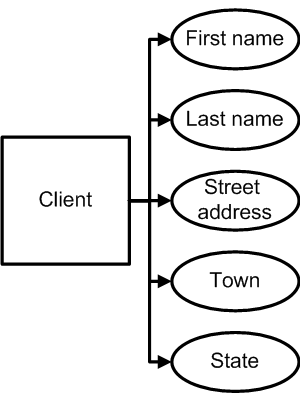
Imagine a simple model as pictured in the diagram on the right.
The model requires that the database store fictional characters (as the entities). For each fictional character it should store their name, address, town and state (as the attributes).
There are no relations here: we store only one type of entities and their attributes.
As I already said earlier, the ER model specifies what should be stored and the database design (relational model in this case) decides how. One ot the benefits of the relational model is that is can construct the data representation on the fly, using SQL statements. That's why there is more than one way to design a storage model, and as long as it's possible to retrieve the data in expected form, every storage model is just as good.
One of the possible ways to implement this ER model in a relational database is to store the entities and their attributes in one table, like this:
| ID | First Name | Last Name | Address | Town | State |
|---|---|---|---|---|---|
| 1 | Marty | McFly | 9303 Lyon Estates | Hill Valley | CA |
| 2 | Arnold | 4040 Vineland | Hillwood | WA | |
| 3 | Hank | Hill | 123 Rainey Street | Arlen | TX |
This table serves two purposes: it both defines an entity and stores its attributes. The entities are defined by being listed in a table with their id (a value being used in the relations) defined as a PRIMARY KEY.
Not all fictional characters, though, have last names. Arnold of Hey, Arnold! does not.
There is one more way to implement this model: store the entities and attributes in two (or even more) separate relational tables. If an attribute is rarely set or rarely used, it can be offloaded into another table:
| ID | First Name | Address | Town | State |
|---|---|---|---|---|
| 1 | Marty | 9303 Lyon Estates | Hill Valley | CA |
| 2 | Arnold | 4040 Vineland | Hillwood | WA |
| 3 | Hank | 123 Rainey Street | Arlen | TX |
| ID | Last Name |
|---|---|
| 1 | McFly |
| 3 | Hill |
The model remains the same: the last name is an attribute of an entity, possibly undefined; but the relational implementations differ. Nevertheless, we can easily transform one representation to another by issuing SQL queries.
This second one can be transformed to the first one using this query:
SELECT  c.*, ln.LastName
FROM    FictionalCharacter c
LEFT JOIN
        FictionalCharacterLastName ln
ON      ln.id = c.id
and vice versa:
SELECT  c.id, c.FirstName, ln.LastName, c.Address, c.Town, c.State
FROM    FictionalCharacter c
LEFT JOIN
        FictionalCharacterLastName ln
ON      ln.id = c.id
SELECT  c.id, c.LastName
FROM    FictionalCharacter c
WHERE   c.LastName IS NOT NULL
The first model (storing all attributes in one table) seems more simple. Why should one ever use the second solution which is more complex?
The reason is that the relational database, itself being an abstraction, should nevertheless be stored on a real world disk drive and served by a real world software. And when it comes to the real world, as we all know, several trade-offs should be made.
In the world of relational databases there is a convention to use a special value, NULL, to mark the data whose value is undefined, that is not known, not stored or not cared for. This value is not equal (and not even unequal) to any value (including itself), the results of most operators and functions over this value are also undefined.
However, it still should be stored in the database somehow. Most databases optimize it to occupy as few space as possible. Oracle, for instance, stored data in rows of dynamic size, the row itself and each column being prepended with their sizes. If the column count in a given row is less than it should be (i. e. there are fewer columns stored in a row than it is stated in the table definition), all other columns are considered to have the value of NULL. This makes storing NULLS in trailing columns to be free in terms of the disk drive space.
But sometimes NULL still occupies some space. Some systems store the data in rows of fixed length; some use no strict datatypes and therefore should store the database along with each value (rather than relying on the table definition); some (like Oracle) should store the NULL if the column is not trailing, i. e. there are some non-NULL values after it.
This makes the table bigger in size. And the queries that do not return this attribute are slower than they would be were it not for that column, since the data occupies more space and the engine needs to read more datapages.
On the other hand, the queries returning all columns, including that which is rarely used, are faster than they would be were this column stored in a separate table. Extra disk reads and CPU time are required to join these columns into one resulting relation and present it to the querying code.
The relations we get as a result of the queries are exactly same, since the relational databases separate logical presentation from the physical storage. But they do it
does not mean they do it the best way
. They do not know beforehand which query shall we do more often: the one that returns all attributes or the one that omits some of them.
The two queries, one returning the missing attribute and one lacking it, cannot be optimized together. Making one faster usually makes the other one slower. If the attribute is stored only for some, not for all entities, or the attribute is not queried for much often, it may be useful to store it in a separate table on the disk, so that the most used query is faster.
Both these storage methods implement one ER model. It's only the way the attribute is stored is changed, not the way it is presented logically. We can even create a view or a stored procedure that would hide this storage method from the calling application completely.
In a relational database, the ER model defines the number and the possible values of the attributes but not the way they are stored.
The entity should be defined by a relation corresponding the PRIMARY KEY of the entity with all of its attributes. The database can store this relation in a relational table as is or generate it from the several tables on demand. As long as the database is able to do that, the model implementation is considered valid.
Storing something in another table and joining the tables to get the results usually means a relationship (in this case a one-to-one relationship). But in this model it is not a relationship that the separate table defines. It is just a more efficient way to store an attribute.
Attribute or entity?
Back to the model that describes fictional characters:

and its implementation:
| ID | First Name | Last Name | Address | Town | State |
|---|---|---|---|---|---|
| 1 | Marty | McFly | 9303 Lyon Estates | Hill Valley | CA |
| 2 | Arnold | 4040 Vineland | Hillwood | WA | |
| 3 | Hank | Hill | 123 Rainey Street | Arlen | TX |
Here we see an attribute, State, which contains a two-letter state code.
Now, what if we want to select all characters who live in states with population less than 10,000,000?
We don't keep information about the population of the U.S. states in our model. We will need to add it to the model somehow.
We could possibly add an additional attribute, StatePopulation, that would show the population of the state the character lives in.
However, this is not the best design: whenever we need to reflect a change in state population in our model, we should update the records for all character who live in these states. In addition, we should make sure that all these records are consistent: all characters who live in same state should have same StatePopulation.
It would be wrong if two Hills lived in same Texas with different populations. StatePopulation is a property of a state, not that of a person who lives in that state.
But the entity-relationship model does not allow adding attributes to attributes. Instead, we should make State an entity, define a many-to-one relationship between the persons and the states and keep the Population as an attribute of a State.
Here's how the new model would look:
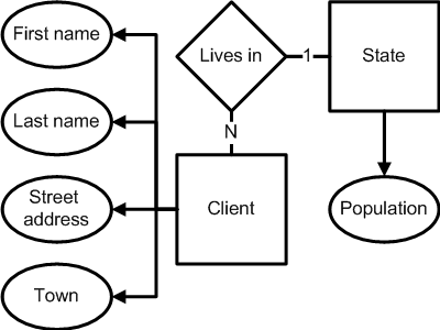
This process is usually called normalization. However, normalization is relational concept, not the ER concept. Here is the definition of the third normal form (which was what we made here) from Wikipedia:
The third normal form (3NF) is a normal form used in database normalization. 3NF was originally defined by E.F. Codd in 1971. Codd's definition states that a table is in 3NF if and only if both of the following conditions hold:
- The relation
R(table) is in second normal form (2NF)- Every non-prime attribute of
Ris non-transitively dependent (i.e. directly dependent) on every key ofR.
As we can see, there are a lot of things in this definition that the ER model knows nothing about: relations, keys, tables. But the ER model has a similar concept: attributes cannot have the child attributes, entites can. If you want to define an attribute for an attribute, promote the latter to an entity and define the relationship. Transitive dependence
is just another name for an attribute of an attribute
.
Here is how this new ER model could be implemented in a relational database:
| ID | First Name | Last Name | Address | Town | State |
|---|---|---|---|---|---|
| 1 | Marty | McFly | 9303 Lyon Estates | Hill Valley | CA |
| 2 | Arnold | 4040 Vineland | Hillwood | WA | |
| 3 | Hank | Hill | 123 Rainey Street | Arlen | TX |
| State | Population |
|---|---|
| CA | 36,756,666 |
| TX | 24,326,974 |
| WA | 6,549,224 |
To select all characters who live in states with population less than 10,000,000, we just issue the following query:
SELECT FictionalCharacter.*
FROM FictionalCharacter
JOIN State
ON State.State = FictionalCharacter.State
WHERE State.Population < 10000000
[/sourcecode]
Now lets see what have we changed here.
In the ER model:
<ul>
<li><code>State</code> became an entity</li>
<li>One attribute, <code>State</code> was removed from <code>FictionalCharacter</code></li>
<li>An additional relationship appeared: <code>FictionalCharacter</code> <em>lives in</em> <code>State</code></li>
<li>An additional attribute, <code>Population</code>, was added to <code>State</code></li>
</ul>
In the relational model:
<ul>
<li>One additional table, <code>State</code>, appeared.</li>
<li>One constraint, a <code>FOREIGN KEY</code> referencing <code>State</code>, was added to the <code>FictionalCharacter</code></li>
</ul>
Nothing had changed in the original table except for the <code>FOREIGN KEY</code> constraint added to ensure the data integrity.
We see that promoting the <code>State</code> to an entity didn't affect the original table. The field <code>State</code> remained. The only thing that changed for this attribute that it now refers a record in the new table, <code>State</code>, that both defines the list of states and holds the state populations.
This is because relational model (unlike ER model) does not really distinguish between the attributes and entities.
Relational model stores relations between the simple types (like integers and strings). A real world relational database stores relations between the integers and strings that describe some real world data.
A U.S. state does not become less of an entity, be it listed as an entity or as an attribute in the ER model. If it's enough for us to know only the state code (which is used in the relational model to represent the state in the relations stored in the database), we can store it in an unconstrained field; if it is not, we should create a separate table for it and constrain the value of the field using a <code>FOREIGN KEY</code>.
In this very case it's easy to tell that there is a relation by looking into the table structure. There is a <code>FOREIGN KEY</code> that gives us a hint that the <code>State</code> is actually a field defining a one-to-many relationship, not a mere attribute.
But's let's consider another model:
<img src="https://explainextended.com/wp-content/uploads/2009/10/GoodsBonuses.png" alt="Goods and Bonuses" title="Goods and Bonuses" width="600" height="300" class="aligncenter size-full wp-image-3511 noborder" />
This model described goods and price-based bonuses. The price ranges should be contiguous and the last range should have no upper bound.
Here's how it would look in a relational database:
<table class="excel">
<caption>Goods</caption>
<tr><th>ID</th><th>Name</th><th>Price</th></tr>
<tr><td>1</td><td>Wormy apple</td><td class="double">0.09</td></tr>
<tr><td>2</td><td>Bangkok durian</td><td class="double">9.99</td></tr>
<tr><td>3</td><td>Densuke watermelon</td><td class="double">999.99</td></tr>
<tr><td>4</td><td>White truffle</td><td class="double">99999.99</td></tr>
</table>
<table class="excel">
<caption>PriceRange</caption>
<tr><th>Price</th><th>Bonus</th></tr>
<tr><td class="double">0.01</td><td class="double">1%</td></tr>
<tr><td class="double">1.00</td><td class="double">3%</td></tr>
<tr><td class="double">100.00</td><td class="double">10%</td></tr>
<tr><td class="double">10000.00</td><td class="double">30%</td></tr>
</table>
Does the <code>PriceRange</code> table really define the price range entities?
Sure it does. It contains all required information: the <code>StartPrice</code> (as a field), the <code>EndPrice</code> (as the same field in the <em>next</em> record in <code>PriceOrder</code>) and the <code>Bonus</code> (as a field in the record that defines the <code>StartPrice</code>). It is possible to write a query that would return a classical relation with all three attributes in one record:
SELECT Price AS StartPrice,
(
SELECT MIN(Price)
FROM PriceRange NextRange
WHERE NextRange.Price > CurrentRange.Price
) AS EndPrice,
Bonus
FROM PriceRange CurrentRange
Due to the way the entity is defined, it is impossible to put a FOREIGN KEY constraint to a price range. The entity price range
is not even being defined by a relation stored in a database: instead, a more simple relation is stored, which corresponds the value of the attribute (Bonus) with a lower bound of the price range.
To build the relation which would correspond each good with its price range and the bonus, we should issue the following query:
SELECT *
FROM Goods
JOIN PriceRange
ON PriceRange.Price =
(
SELECT MAX(Price)
FROM PriceRange
WHERE PriceRange.Price <= Goods.Price
)
[/sourcecode]
We could probably use a more formalistic approach to the problem: store PriceRange in a table with a surrogate PRIMARY KEY, the lower and upper bounds as the attributes; and store a FOREIGN KEY reference to it in Goods.
This design would be more familiar but it could easily lead to data inconsistency. What if the Price of a good is not within the PriceRange the good references? What is the price ranges are not contiguous? What if the price ranges values are updated and the referencing columns are not?
The root of this problem it that the mechanisms to ensure referential integrity work on declared relationships, i. e. those just listed in a table, while what we deal with here is an inferred relationship.
The relationship between a good and a price range is not defined by a mere declaration of the fact that the relationship exists, i. e. it is not taken from the outside world. Instead, whether the relationship exists or not is defined by the values of the attributes of a good and a price range. It is generated from the other information stored in the database. And the relational databases, as I already said above, can transform the relations they store in the tables to other relations, using the relational algebra, mathematical operators and other means.
This relational design implements the ER model more consistently and efficiently, and this implementation is less prone to errors. However, using this design, we cannot use automated tools to map the relational model back to the ER model anymore. We don't define the PriceRange and both of its attributes using a single stored relation referenceable with a FOREIGN KEY. From the relational model's point of view, the Price is just an attribute of a Good which has no reference to the PriceRange. Nevertheless, the PriceRange is an entity with its attributes (which can only be represented by self-joining the table), and Price is used to reference it.
The fact that this design is more consistent, however, does not mean that the original design should never be used. Database normalization helps to cope with the possible inconsistencies in the model by inferring relations rather than storing them, but this can require additional resources (memory, CPU etc) and therefore be less efficient. There are numerous situations which require to store relations in a way that allows possible logical inconsistencies but is faster to query. Keeping the model consistent now becomes a developer's task but it is the price one has to pay for speed. This process is called denormalization.
I will not discuss benefits and drawbacks of normalization and denormalization in this article. What I wanted to say is that usually there are many ways to implement an ER model in a relational database and not all these methods can be easily mapped back to the ER model which clearly distinguishes between entities, attributes and relationships.
A relational model uses same datatypes to represent entities and to define attributes. Therefore, it is best thought of as a way to store relations between the entities of the real world (represented by the numbers and strings), some of which are not of interest enough to be the entities of the model.
Whether the values the table relates represent entities or attributes is not a concern of a relational model. It can store and return both with equal efficiency.
Relationship or entity?
Consider this model:
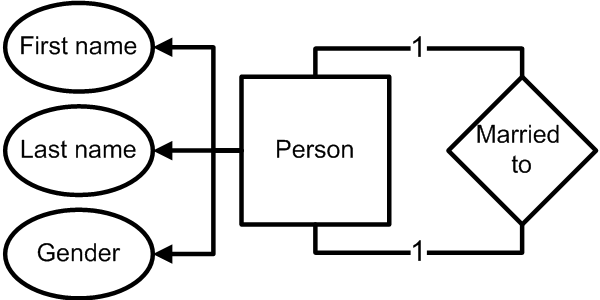
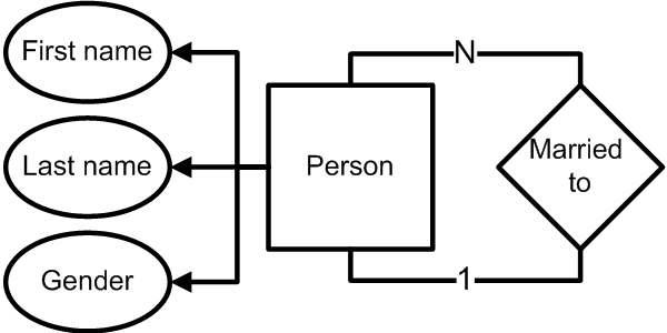
It describes fictional persons who are married to each other.
This can be implemented in a relational database as this:
| ID | Gender | First Name | Last Name |
|---|---|---|---|
| 1 | M | Desmond | Jones |
| 2 | F | Mary | Jones |
| ID | Husband | Wife |
|---|---|---|
| 1 | 1 | 2 |
Here we see that Desmond Jones is married to Mary Jones. Marriage of course is relationship (and is called so even outside the database world).
That's fine. Now we want to add Scarlett O'Hara into the model. She was married first to Ashley Wilkes, then to Rhett Butler.
The model as it is now does not let us do it, since a marriage is a one-to-one relation (at least in the Christian tradition). We should change this relation to a many-to-many (which changes its wording from is married to to has ever been married to).
Here's how the new model would look like:
| ID | Gender | First Name | Last Name |
|---|---|---|---|
| 1 | M | Desmond | Jones |
| 2 | F | Mary | Jones |
| 3 | M | Ashley | Wilkes |
| 4 | M | Rhett | Butler |
| 5 | F | Scarlett | O'Hara |
| ID | Husband | Wife |
|---|---|---|
| 1 | 1 | 2 |
| 2 | 3 | 5 |
| 3 | 4 | 5 |
The ER model changed the relationship from one-to-one
to many-to-many
.
To reflect this, the relational model dropped the separate UNIQUE constraints on Husband and Wife and added a composite UNIQUE constraint on (Husband, Wife).
Now, let's the add two more persons to our model: Ransie and Ariela Bilbro from O. Henry's The Whirligig of Life. They married each other twice.
This time even changing the relationship type in the ER model won't help. There is no such thing as a double relationship
. To reflect the double marriages, the relationship should be promoted to a first-class entity with one-to-one relation to either part (which now means been in this marriage).
The model would look like this now:
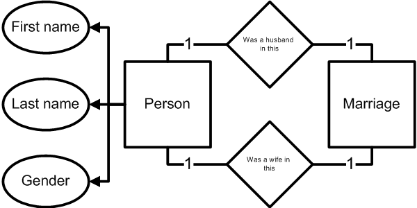
We see that the ER model changed significantly. How did the relational model change?
Since the husband and wife do not uniquely define the marriage anymore, the UNIQUE constraint should be dropped from the Marriage, but otherwise the tables remains the same:
| ID | Gender | First Name | Last Name |
|---|---|---|---|
| 1 | M | Desmond | Jones |
| 2 | F | Mary | Jones |
| 3 | M | Ashley | Wilkes |
| 4 | M | Rhett | Butler |
| 5 | F | Scarlett | O'Hara |
| 6 | M | Ransie | Bilbro |
| 7 | F | Ariela | Bilbro |
| ID | Husband | Wife |
|---|---|---|
| 1 | 1 | 2 |
| 2 | 3 | 5 |
| 3 | 4 | 5 |
| 4 | 6 | 7 |
| 5 | 6 | 7 |
This happened because the marriage in fact is an entity, with its own attributes like date and place of the wedding, the number of guests invited, awful toasts made, tea sets presented etc. But the ER model was not initially interested in all this and the marriage was declared as a relationship, not an entity.
In ER model, a relationship between two entities can either exist or not exist, one or the other. There cannot be such thing as a double relationship
or expired relationship
. To trace such things one should need to promote a relationship to an entity and assign the attributes to it.
However, the relation model can handle this easily. The way the relationship is build in our implementation, there is no clear disctinction between a marriage as a relationship and a marriage as an entity. By putting and removing UNIQUE constraints, Marriage can be easily changed to represent a one-to-one relationship, a many-to-many relationship or even an entity and two one-to-one relationships at once, the relational struсture still remaining the same.
Summary
The entity-relationship model defines what should be stored in a database: about what, which information, how related. This should be described in terms of entities, relationships and attributes.
A relational model describes how to implement the requirements of the ER model: which information should be stored in which relational tables.
The relational model is very flexible and can construct relations on the fly. The relations can be stored in one way and represented in another way. This helps in handling more complex models that require the relationships to be inferred rather than stored. The database can thus be made more maintainable and less prone to logical inconsistencies.
Since the relational model just defines relations between simple types like integers and strings, things like entities, attributes and relationships are not a concern of a relational model. It only implements the requirements established by the entity-relationship model.
Usually it does it using simple and formal mechanisms: a PRIMARY KEY-preserved table to define entities and attributes, and a separate table with FOREIGN KEY references to define the relationships.
However, it can change the storage methods: move the attributes and relationship between the tables, define the entities so that the attributes should be calculated, etc. This can be done both to improve efficiency and to get rid of inconsistencies.
Since relational model separates storage from presentation by using a built-in relation transformation language, SQL, any storage method is valid as long as it is able to construct the entities, attributes and relationships in their canonical form.
That's why it makes no sense to speak of the entities, relationships and attributes in respect to the relational model. These things are defined by the entity-relationship model.
 Subscribe in a reader
Coming from Oracle Designer – what you’ve referred to as the “ER model”, I’ve known as the “Logical ERD” while the “relational database [model]” was called the “Physical ERD”. The difference isn’t immediately obvious on simple models, but if you compare the attributes/columns, foreign key(s) won’t show be in the attribute list – they would be in the physical model because the resulting table was generated. Another thing on the Logical model was that optional columns would be noted. Logical models would also show arcs, and the term escapes me but tables encapsulated by tables to show attribute inheritance…
I haven’t seen the diagram format you mention, using diamonds – only rectangles and crowsfeet. The rules to crowsfeet were that they pointed either down or to the East (right). The lines were dotted to indicate optional relationships, and the crowsfeet attached to a table to show a many relationship – crowsfeet on either end would mean “many-to-many”. Also, lines shouldn’t cross if they don’t have to.
The diagram feature in SQL Server Management Studio is an example of a physical model. Likewise for the no longer supported Visio Modeller app.
rexem
20 Oct 09 at 09:15
@rexem: Diamonds for a relationship are used in Chen’s notation. This allows relationships to have their own attributes and relationships (like, say, a marriage date in the example above).
However, a relationship still needs to be uniquely defined by the entities related, which distinguishes it from an entity.
Quassnoi
20 Oct 09 at 13:50
Social comments and analytics for this post…
This post was mentioned on Twitter by HybridDBA: Nice ERD overview / review: http://bit.ly/Voj8Q…
uberVU - social comments
22 Nov 09 at 11:43
Hi, I’m using the following format to design ER, after all it looks much alike the Table Structure design.
http://www.meds-sdmm.dfo-mpo.gc.ca/meds/Prog_Nat/NCIS/Definition/Ncis_ER_diagram.gif
(found this on google)
I’m wondering what’s the difference between ER and Table structure.
Thanks
Praveen
5 Dec 09 at 08:35
@Praveen: with ER, you should define entities, relationships and attributes. The diagram in the link you provided shows the relational design which provides the tables layout (so that we can generate a database schema) but gives too few hints on what will be stored in the tables. What is Long_Fields on diagram above? Is it an entity or a relationship or an offloaded attribute? You cannot tell from the name of the fields and the table design.
Quassnoi
5 Dec 09 at 16:08
Thanks a lot for this great article. The first time I really feel I have understood what an ER-Diagram really is all about and how it works. I came here through StackOverflow.com.
May I ask, what tool did you use to create those diagrams?
openfrog
29 Dec 09 at 16:27
@openfrog: MS Visio.
Quassnoi
29 Dec 09 at 16:30
Very, very good article.
Just a note: do the arrows between the attributes in the marriage diagrams represent any concept, or have you just missed those?
Gonçalo
1 Mar 10 at 03:10
@Goncalo: no, just missed :)
Quassnoi
1 Mar 10 at 11:17
Would MS Access be a viable candidate in smaller applications? It does much of the work for you. There are some Great mapping programs that can also interact with it, such as Visio.
How different is ER from some of the Process Improvement tools used for Lean & Six Sigma and Project Management?
John Ross
22 Dec 11 at 06:55
@John: ER is a model of data organization. It’s not a tool (as in software tool). I don’t know what Lean & Six Sigma is, and project management is completeley unrelated to ER. Yes, MS Access is a viable solution for small applications.
Quassnoi
22 Dec 11 at 11:50
This is a very good explanation, best i found. Thanks
vimal krishna
26 Jan 12 at 13:21